1961 film, 'Remote Repair and Modification of the HRE-2 Core Vessel' digitized

By Dr. Nick Touran, Ph.D., P.E., 2023-07-05, Reading time: 24 minutes
We’re super excited to announce the recent digitization of a 1961 film detailing a major repair of the Homogeneous Reactor Experiment-2 (HRE-2), a fluid-fueled aqueous homogeneous reactor at the Oak Ridge National Lab in Tennessee This reactor was an early predecessor to molten salt reactors. This is the third of four historical nuclear films in our latest batch of 4K digitizations from 16mm film at the National Archives.
HRE-2 developed a hole that leaked fluid fuel from the core region into the heavy water blanket region. They adjusted procedures and operated in this condition for a while. Later, it developed a second hole and they decided to repair it. This film shows highly specialized tools and equipment allowing them to diagnose and repair the holes remotely. Inside the core the radiation dose rate was a nearly-unbelievable 100,000 R/hr.
I read the story of the HRE-2 vessel leak many years ago in Alvin Weinberg’s autobiography (pg 124), so when I learned that there was an old video describing its repair, I knew it had to be digitized. This is an extremely rare film that probably hasn’t been viewed by hardly anyone since the 1960s… until today!
Catalog description: Illustrates the remote repair and modification of the HRE-2 core vessel, following the formation of two holes which permitted transfer of fuel to the blanket side of the reactor. Shows how special equipment had to be designed for repairing the HRE-2, and the problems involved in working with the reactor where the radiation level in the vessel was greater than 100,000 Roentgen per hour.
This is film 88244 in our catalog.
Show transcript
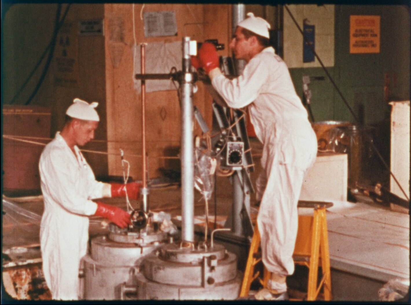
| 00:00 | The highly radioactive core vessel of homogeneous reactor experiment number two, |
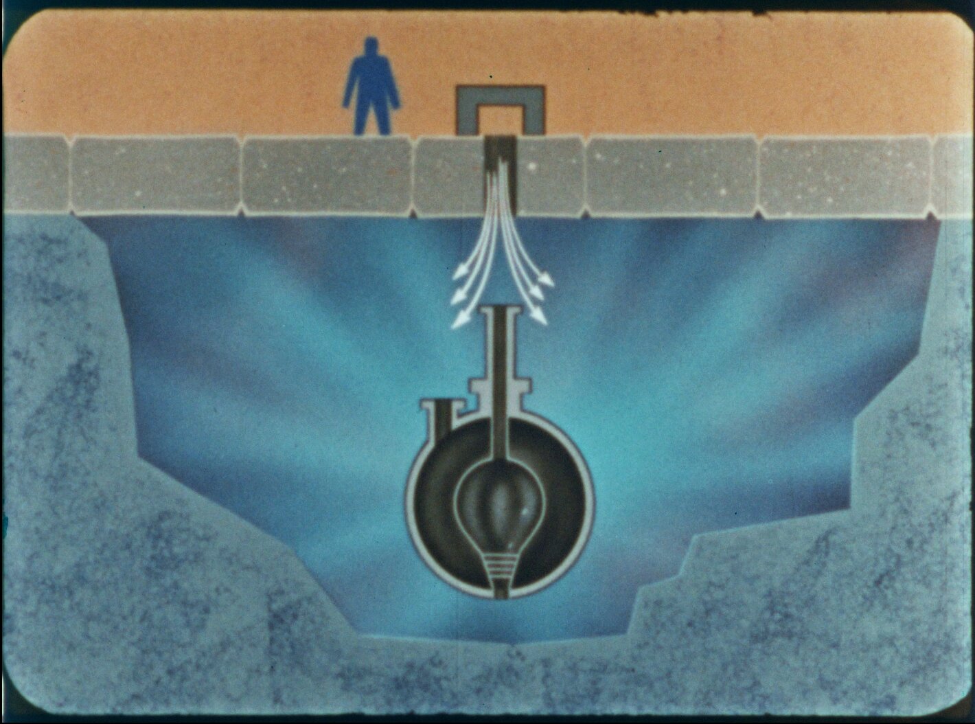
| 00:25 | known as HRE2, lies out of sight 20 feet below the thick concrete blocks |
| 00:31 | on which these men are standing. |
| 00:34 | They work under the most restricted conditions, at times with a periscope providing limited visibility, |
| 00:41 | at other times with no view of the work below. |
| 00:48 | The men are manipulating tools that reach down into the core vessel. |
| 00:53 | They are repairing and modifying the vessel to improve the reactor's operational behavior. |
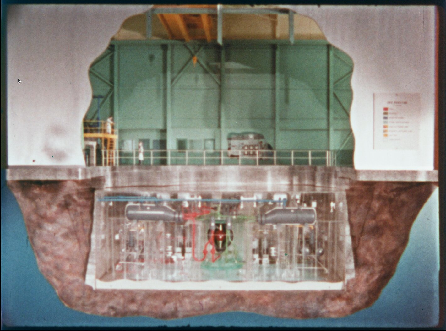
| 01:02 | Homogeneous Reactor Experiment No. 2 began its nuclear operation in this building |
| 01:06 | at Oak Ridge National Laboratory in December 1957. |
| 01:14 | This cutaway model of the building shows the reactor in its cell below ground level. |
| 01:20 | operation of hre2 provides information regarding the feasibility of homogeneous power reactors |
| 01:27 | fueled with an aqueous solution hre2 was designed as a five megawatt two region reactor consisting |
| 01:37 | of core and blanket systems a pump continuously circulates a dilute heavy water solution of |
| 01:45 | urinal sulfate, copper sulfate, and sulfuric acid, through the core where |
| 01:51 | fissioning occurs, and heat is generated at temperatures up to 300 degrees |
| 01:57 | centigrade. Past a pressurizer, which provides system pressures up to 2,000 |
| 02:04 | pounds per square inch, through a heat exchanger where heat is released and |
| 02:09 | and steam is produced to drive the turbine generator. |
| 02:16 | The fuel circulates back through the core vessel at a rate of 400 gallons per minute. |
| 02:24 | Uranium in the fuel solution is highly enriched in the 2,35 isotope. |
| 02:29 | The dissolved copper sulfate is a catalyst or recombination of radiolitic gas. |
| 02:35 | The blanket system contains a pump, a pressurizer, and a heat exchanger similar to those in the |
| 02:49 | fuel system. |
| 02:54 | Blanket fluid circulates in the space between the core vessel and the pressure vessel at |
| 02:59 | a rate of 230 gallons per minute. |
| 03:02 | This fluid is heavy water, which serves as a neutron reflector. |
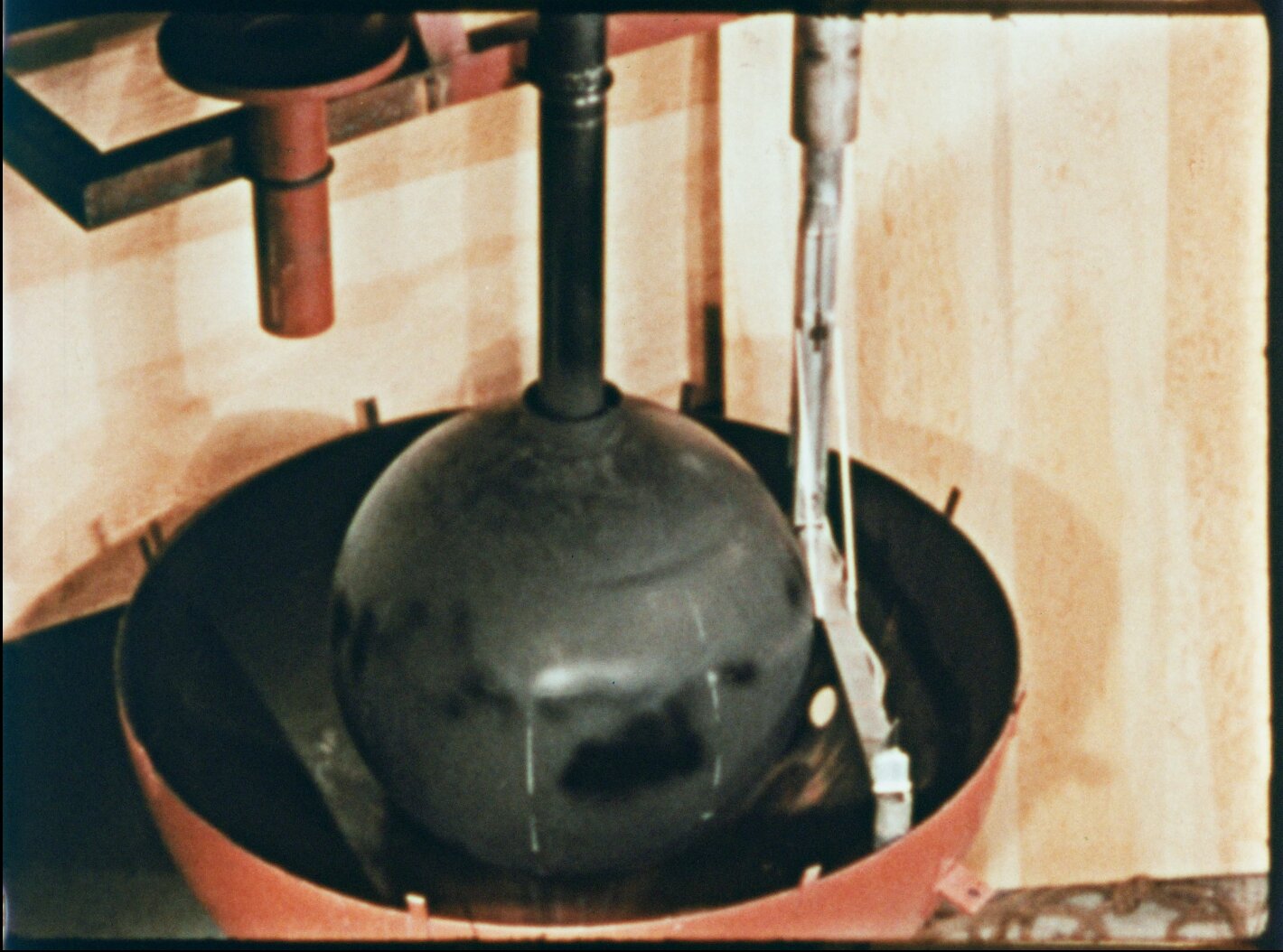
| 03:09 | The welded core vessel, the first large Zircaloy vessel ever made, was an experiment in both |
| 03:16 | fabrication and application. |
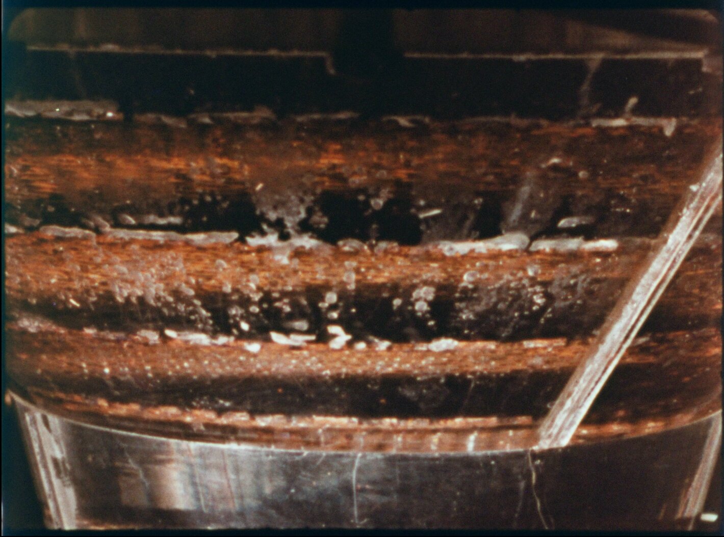
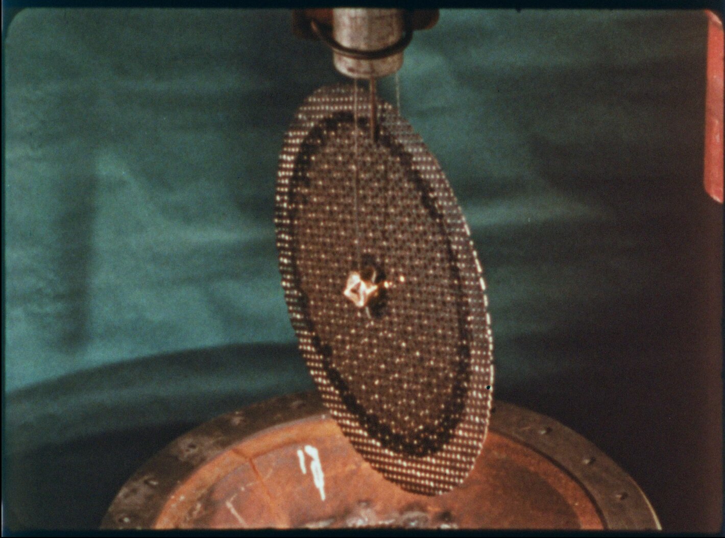
| 03:19 | The conical inlet section contains nine perforated plates to diffuse the solution and provide |
| 03:27 | slug flow through the sphere. |
| 03:33 | The reactor was operating at design conditions of 5 megawatts when, in April 1958, a hole |
| 03:40 | formed in the core vessel and allowed fuel solution to transfer to the blanket system. |
| 03:50 | Reactor operating procedures were revised to permit operation with fuel in both the |
| 03:55 | the core and blanket systems. Without changes in equipment or piping, the operation continued |
| 04:02 | for two years. Six long runs, the last for 105 days of continuous operation, were made |
| 04:11 | in accomplishing most of the original objectives. At the end of this period, a second hole formed |
| 04:18 | in the core vessel. |
| 04:21 | After formation of the first hole, considerable remote viewing was done inside the vessel |
| 04:27 | while the reactor was shut down between runs. |
| 04:32 | It was found that several diffuser plates were loose, but the hole was below the top |
| 04:37 | five plates and could not be viewed from inside the core. |
| 04:43 | By use of this special viewing device, |
| 04:47 | lowered into the blanket region, |
| 04:50 | the outside wall of the core was inspected to determine whether the hole originated |
| 04:54 | from a weld failure, a metal defect, |
| 04:58 | or from some other cause. |
| 05:02 | This is the hole as seen in the mirror of the blanket viewing device. |
| 05:07 | It was concluded that the failure was probably due to a melt through. |
| 05:13 | Further full-scale hydrodynamic tests were made to verify the mechanism whereby such |
| 05:23 | a melt through might occur and to develop an improved core flow pattern. |
| 05:30 | When small metal chips and sand particles were introduced into this mock up of the core |
| 05:35 | vessel, it was determined that there were local regions of flow separation and low velocity |
| 05:41 | along the wall of the diffuser cone on the upper diffuser plates and along the wall of |
| 05:47 | the lower portion of the hemisphere. |
| 05:51 | Uranium absorbing scale might accumulate in these regions and increase the temperature |
| 05:56 | of the fluid to a point where boiling and chemical phase changes could cause further |
| 06:01 | uranium deposition and melting of the diffuser plates and the core wall. |
| 06:09 | When some of the plates were loosened, as in the reactor, they were floated by hydraulic |
| 06:13 | forces and created non-uniform flow distribution. |
| 06:21 | Particulate material still accumulated along the wall when the flow direction was reversed. |
| 06:28 | With plates removed from the 90-degree cone and with flow in the normal direction, there |
| 06:33 | were still areas where scale-like particles could accumulate. |
| 06:38 | with the flow reversed and the plates removed, the particulate material did not collect along |
| 06:44 | the wall. Although the flow distribution is not ideal, turbulence in the vessel should |
| 06:51 | provide acceptable cooling of the wall. Any corrosion scale on the wall should be removed |
| 07:00 | at low solution flow velocities. Combined results of hydrodynamic studies, operation |
| 07:06 | of the reactor and visual observations led to certain conclusions. It was decided to |
| 07:15 | modify and repair the core vessel. The top five diffuser plates would be removed. Corrosion |
| 07:25 | products and uranium bearing scale would be cleaned from the core wall. Wall thickness |
| 07:32 | thickness would be measured ultrasonically. A specimen from the wall in the region of the |
| 07:40 | second hole would be removed for metallographic examination to verify that the holes had resulted |
| 07:47 | from melting of the wall. The hole would then be taper reamed to prepare it for plugging. Both |
| 07:58 | Both holes would be patched. |
| 08:05 | And the direction of flow would be reversed so that fuel solution would enter at the top. |
| 08:13 | This work had to be done under extremely restricted conditions. |
| 08:17 | The only access to the vessel assembly is through small flanged openings. |
| 08:26 | The blanket access is three and a half inches in diameter, and the core access is only two |
| 08:33 | and an eighth inches. |
| 08:35 | The radiation level in the empty vessel is greater than 100,000 rontgens per hour, permitting |
| 08:42 | approach only through five foot thick concrete shielding plugs. |
| 08:48 | These plugs are 20 feet above the lower portion of the vessel. |
| 08:54 | In the working area, airflow must be carefully controlled because much of the contamination |
| 09:00 | is loose particulate matter. |
| 09:02 | Furthermore, the intensely radioactive particles contaminate any tools placed in the vessel. |
| 09:11 | To accomplish the objectives under these conditions, special devices and tools were designed and |
| 09:17 | built. |
| 09:20 | And in this dimensionally accurate mock-up, the devices were thoroughly tested and programmed |
| 09:26 | before use in the reactor. |
| 09:30 | Devices were developed for viewing and inspecting both the inside and the outside of the core |
| 09:35 | vessel. |
| 09:37 | For viewing within the core vessel, a periscope seven-eighths of an inch in outside diameter |
| 09:44 | and 21 feet long was developed by Lerma Engineering Corporation. |
| 09:50 | It contains cerium-stabilized radiation resistant lenses |
| 09:55 | and is equipped with interchangeable objective elements. |
| 09:59 | The lenses provide a 180 degree field of vision straight down |
| 10:04 | or a 30 degree field at a right angle. |
| 10:09 | Detailed examination of the vessel as well as assistance with some of the operations, |
| 10:15 | was provided by this instrument. |
| 10:19 | Lighting was supplied separately by 500 watt projector lamps |
| 10:23 | caged and mounted on 1⁄4 inch tubing. |
| 10:28 | In some instances, viewing was essential, but room in the 2 and 1⁄8 inch opening |
| 10:34 | could not be spared for lights and a periscope. |
| 10:38 | A device was therefore developed at Oak Ridge National Laboratory, which incorporated a |
| 10:43 | zirconium oxide arc lamp and lens system to project a beam of light through a hole in |
| 10:49 | a mirror to the area to be viewed. |
| 10:53 | The reflected image is viewed in the mirror with a monocular. |
| 10:59 | Several operations inside the core were guided by viewing devices which permitted looking |
| 11:04 | into the holes from the blanket side. |
| 11:07 | The blanket viewing device, shown being tested in the mock-up, had to enter the blanket vessel |
| 11:13 | through a 3 1⁄2-inch pipe. |
| 11:16 | Then it had to reach behind the core vessel with a horizontal 30-inch arm carrying 200 |
| 11:21 | watts of lighting and a scanning mirror. |
| 11:25 | The device has a monocular and fixed mirror at the top with a fixed mirror and a rotating |
| 11:31 | mirror at the bottom. |
| 11:35 | articulated manipulator carrying a miniature television camera was |
| 11:39 | developed. The device has three hydraulically operated elbows and one |
| 11:45 | wrist and can be programmed to any spot on the core vessel. Manipulators were |
| 11:52 | made to accurately position ultrasonic transducers for measuring the thickness |
| 11:57 | of the spherical and conical sections of the core wall. Measurements made during |
| 12:04 | the life of the reactor along with original fabrication data permit |
| 12:09 | periodic determination of corrosion rates working tools for each operation |
| 12:17 | were designed built and thoroughly tested in a mock-up the first mechanical |
| 12:24 | operation was to have been the cutting of diffuser plates free from the vessel |
| 12:28 | wall by use of milling cutters and saw blade segments these tools were not used |
| 12:36 | in the reactor because the plates were found to be already loose the plates |
| 12:43 | range from 10 to 22 inches in diameter since the access is only two and an |
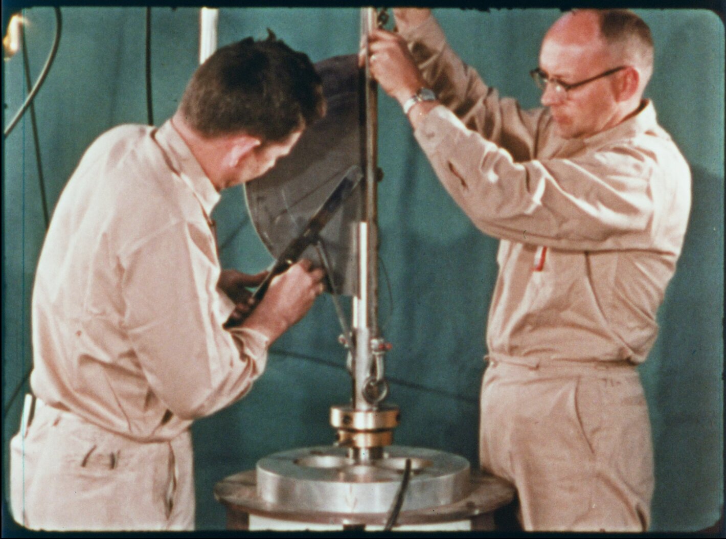
| 12:50 | eighth inches in diameter this miniature heliar cutting torch and manipulator |
| 12:57 | were devised to cut the plates into narrow strips. |
| 13:03 | A protective angle iron supports the fragile manipulator during handling. |
| 13:09 | The angle iron is removed and the torch is lowered into position in the mock-up. |
| 13:17 | The operator with no view of his work lowers the manipulator hook to pick up the top plate. |
| 13:24 | plate, 22 inches in diameter, is raised, is lowered over the ground electrode clamp, falls |
| 13:36 | into position, and is latched. Cuts are then made as simulated here. Gauges assure that |
| 13:46 | each strip will be one and a half inches wide. A check run is made after each cut to guarantee |
| 13:53 | that the cut was complete. The operator controls the torch by instruments, the width of the |
| 14:01 | cut by gauges and the length of the cut by a travel indicating scale. The actual cutting |
| 14:10 | is done underwater and the procedure was thoroughly demonstrated at the test station. At the reactor |
| 14:17 | In eight hours, three plates were lifted, latched, and cut. |
| 14:30 | The radioactive strips are fished from the vessel with the aid of the projected light viewer. |
| 14:36 | Five plates were cut, and the strips were fished from the core vessel in two weeks. |
| 14:41 | The strips were deposited in a carrier above the core access |
| 14:44 | flange and below the shielding plugs. A variety of articulated tools were built for removing |
| 14:52 | objects from the vessel. The core was cleaned and descaled with an ordinary wire brush driven |
| 15:01 | by a small air motor. The brush and motor are mounted on a manipulator, which presses |
| 15:07 | the brush against the core wall. |
| 15:13 | Consecutive overlapping passes are made over the spherical and 90 degree conical portion |
| 15:18 | of the vessel. |
| 15:20 | An impression device obtained exact dimensional definition of both holes. |
| 15:26 | Each impression was made by a thermoplastic block electrically heated and then driven |
| 15:31 | into the hole by an air cylinder. |
| 15:35 | device is lowered into the core vessel mock up to previously calibrated points. |
| 15:39 | The arm is raised and the operator searches for the lower hole with the tip |
| 15:44 | of the impression device. His only view is through the blanket viewing device. |
| 15:51 | When the operator finds the hole, he extends the air cylinder and drives the |
| 15:57 | block. Satisfied with the alignment, he withdraws it, heats the plastic, drives it into place, |
| 16:07 | permits it to cool, and removes it from the hole. This is a thermoplastic block before use, |
| 16:15 | one that has been driven into the lower hole, a clean replica of the contaminated master, |
| 16:21 | and a zircaloy patch for the lower hole, |
| 16:26 | contour milled using the plastic master. |
| 16:30 | A replica of the upper hole was made to provide the pilot for this specimen removal saw. |
| 16:35 | This tool had a two-fold purpose, to obtain a specimen for metallographic examination |
| 16:42 | and to perform one step in the preparation of the hole for plugging. |
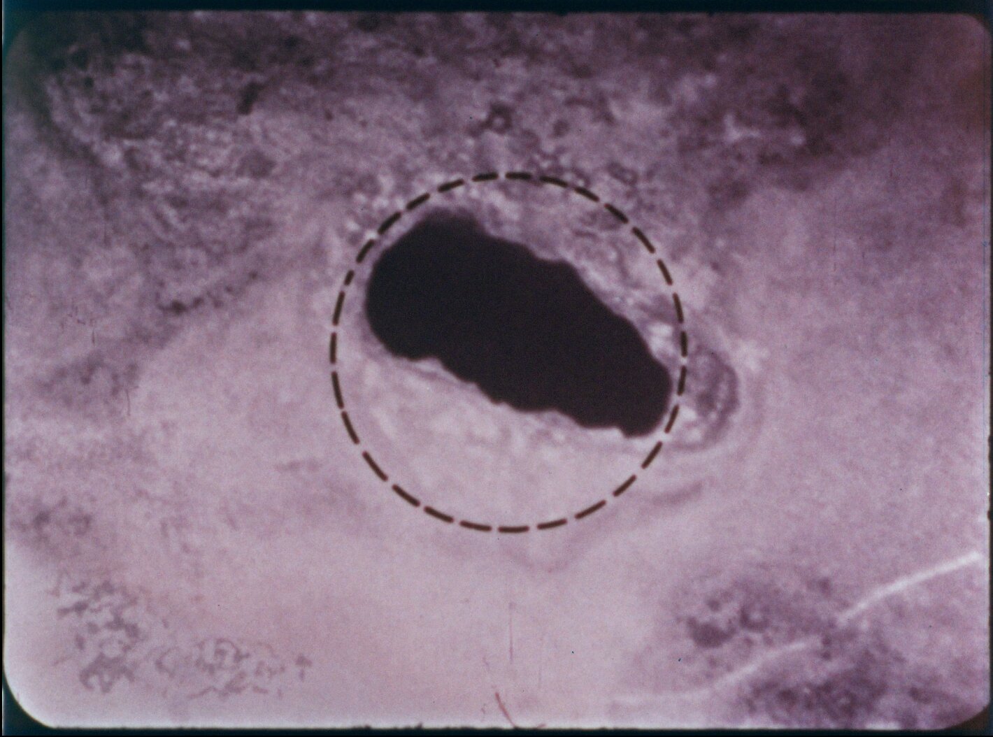
| 16:47 | This is a photograph of the upper hole as formed and this picture shows the hole after brittle |
| 16:57 | scale had been chipped away. The circle indicates the area to be removed by the saw. The pilot for |
| 17:06 | the saw had to fit in the hole and provide the front radial bearing. The saw shown in the |
| 17:14 | developmental stage has an erecting mechanism a light a periscope a means for rotating the saw |
| 17:25 | a cylinder for advancing and withdrawing it and a device for retaining the specimen |
| 17:33 | the tool successfully retrieved a specimen for examination and created a round hole |
| 17:40 | as shown by this photograph. |
| 17:46 | This photograph shows the hole after it was reamed to a conical surface by a tool similar |
| 17:51 | to the specimen removal saw. |
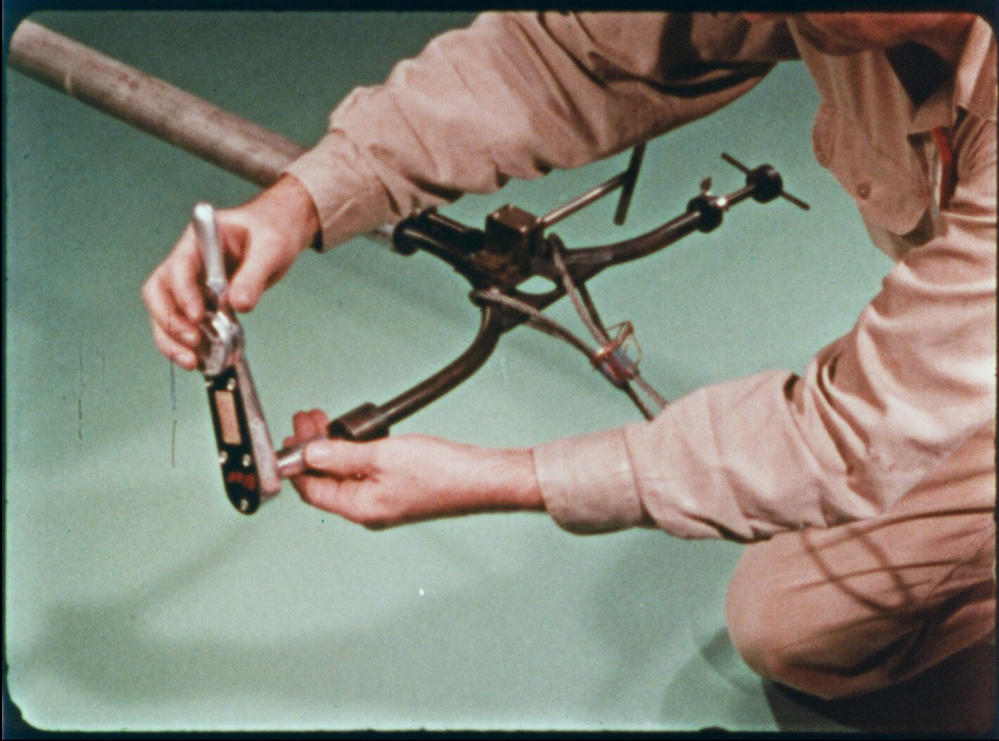
| 17:56 | The patch placement tool performed the final operations. |
| 18:00 | The upper end has the erecting mechanism. |
| 18:08 | the toggle nut placement mechanism, the bolt torquing drive, and the bolt release. |
| 18:30 | At the lower end, mounted for insertion, is the patch with gold gasket and the toggle |
| 18:36 | bolt assembly in the closed position. The tool is erected, the toggle is inserted through |
| 18:43 | the hole, is opened and pulled back against the wall of the vessel for tightening. With |
| 18:51 | the patch insertion tool in position in the mockup, the operator looks into the blanket |
| 18:56 | viewer and aligns the end of the toggle bolt with the hole. The bolt is inserted, it springs |
| 19:05 | is pulled back and tightened. |
| 19:11 | This is the patch for the lower hole as it appears in place in the vessel mock-up |
| 19:16 | and in the reactor. |
| 19:24 | Since the upper hole is in a region of greater heating |
| 19:27 | and lower flow velocity, it is desirable that the patch be set in the tapered hole |
| 19:33 | so as to be flush with the vessel wall. |
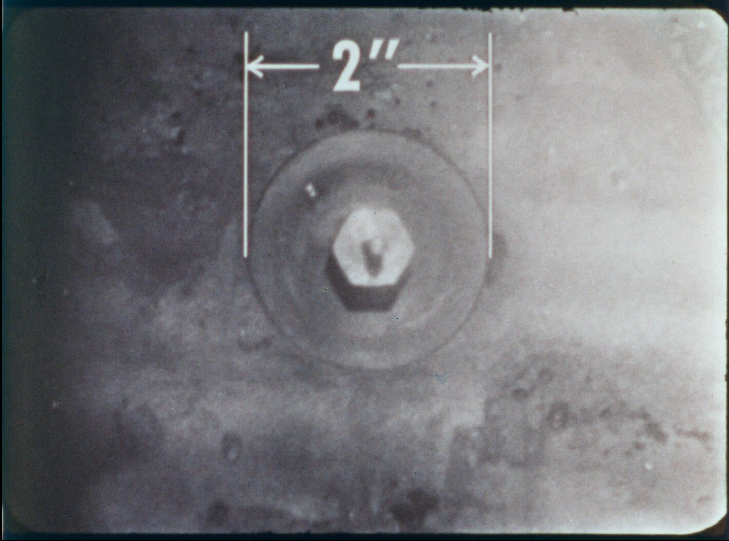
| 19:37 | The zircaloy bolt has a flush countersunk head |
| 19:41 | with a hexagonal wrenching head of nickel brazed to it. |
| 19:46 | The head will dissolve during pre-critical operations, |
| 19:50 | leaving a flush patch and bolt assembly. |
| 19:55 | Here is the patch in place in the reactor vessel |
| 19:58 | before operation of the reactor has dissolved the bolt head. |
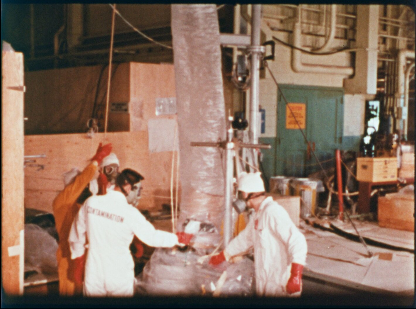
| 20:03 | Because the tools became highly contaminated in use, special procedures and precautions were |
| 20:13 | required to protect the personnel and prevent the spread of particulate contamination. Each |
| 20:20 | tool after having served its purpose had to be withdrawn and disposed of. Contaminated |
| 20:28 | components of HRE 2 had been replaced routinely throughout the reactor's |
| 20:33 | lifetime then beginning in March 1960 work began on repairing and modifying |
| 20:40 | the very heart of the reactor throughout the work there was not a single case of |
| 20:47 | overexposure of personnel to radiation and by August 1960 the last tool had |
| 20:55 | been removed from the core. Despite the radiation hazard, the necessity that only remote tools be |
| 21:03 | used, the limited visibility, and in some cases total lack of visibility, extremely complex |
| 21:11 | mechanical operations were performed in the irradiated core vessel. Thus, the practicality |
| 21:18 | of extremely difficult and totally unanticipated maintenance of circulating fuel reactors |
| 21:25 | was demonstrated. |
| 21:27 | The reactor resumed nuclear operation at low power |
| 21:31 | with flow reversed through the core on November 7, 1960. |
| 21:36 | The degree of improvement in the reactor's behavior |
| 21:39 | will be revealed in continued operation |
| 21:42 | with the remodeled core. |
Thanks to Ross Koningstein for his help in making this happen.
Some stills from the film
Read more about HRE-2
Contents of the film by timestamp include:
- 00:00 Intro
- 01:14 Description of HRE-2 systems
- 03:09 Description of core vessel and first hole
- 04:22 Remote viewing and diagnostics
- 05:02 This is the hole
- 05:18 Full-scale mockup flow tests
- 07:14 Repair and modification plans
- 08:17 Access options and hazards
- 09:10 Development and testing of repair tools
- 10:59 Blanket viewing device
- 11:34 Articulated TV camera
- 12:23 Underwater cutting of diffuser plates
- 14:48 Cleaning tools
- 15:21 Thermoplastic hole impression device
- 16:30 Specimen removal saw
- 17:55 Patch placement tool and patching
- 19:23 Upper hole patch with dissolvable head
- 20:06 Tool contamination precautions
- 20:35 The actual repair
- 21:28 Resuming operation at low power
These are loaded into the youtube video as chapters for your convenience.
See Also
- Our Digital Reactor History Museum
- Our Old Videos page with a running list of the available and yet-to-be-scanned films out there. If you’re interested in helping to get some of these scanned, check out our digitization GoFundMe and/or contact us!
- Tweet announcement of this
About Dr. Nick Touran, Ph.D., P.E.
Nick Touran is a nuclear engineer with expertise in advanced nuclear reactor design, reactor development, and the history of nuclear power. After getting a Ph.D. at the University of Michigan, he spent 15 years at TerraPower in Seattle working on core design, business development, software development, and configuration management. He is now a consultant involved in advising and assisting numerous reactor development and deployment efforts. He is also a licensed professional engineer in Nuclear Engineering.
Nick has been active in public education around nuclear since 2006 as the founder of whatisnuclear.com. He has spoken at numerous institutions, schools, and public events, and was once featured on NPR’s Science Friday. Recently, he has coordinated the digitization of over 45 historical nuclear films.
Reader comments